Quadruped Robot
Each leg of the quadruped robot consists of
three joints (Hip Roll, Hip Pitch, Knee Pitch) and has a total of 12 degrees of
freedom, so it has degrees of freedom suitable for walking both flat
and uneven terrain. Each joint is composed of a brushless DC motor and low gear
ratio, and a timing belt system is applied to reduce moment of inertia of the driving leg such as massless leg.

Fig. 1. MSC
Quadruped Robot and Guide Dog
Nonlinear Model Predictive Control
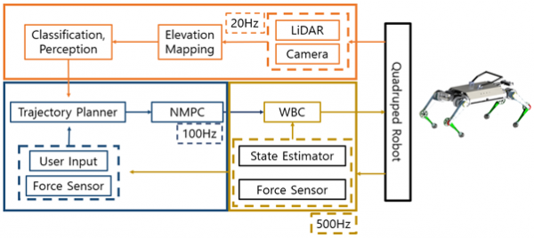
Fig. 2. Diagram of Guide Dog Quadruped Robot Controller
Quadruped robots are widely used in various fields. They have the advantage of being able to navigate various terrains, and their animal-like appearance is becoming increasingly approachable to people. Leveraging these advantages, research is underway to use them as guide dogs for the blind or as helper dogs. In the controller, we are studying both the convex model predictive controller and the nonlinear model predictive controller. Convex MPC demonstrates strength in dynamic movements, while NMPC showcases robust locomotion. To understand the strengths and weaknesses of both Convex MPC and NMPC and to complement each controller's shortcomings for enhanced performance, we are developing a foot swing trajectory planner, external force estimation, and compact force sensors to research a controller suitable for guide dogs for the blind. The details are as follows.
Dual Locomotion Pipe Inspection Robot
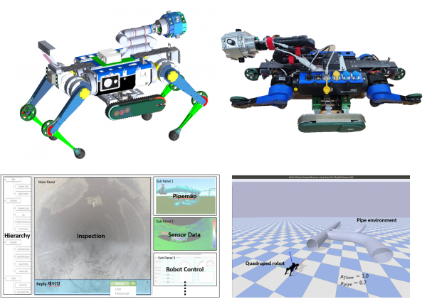
Fig. 3. MSC Pipe Inspection Robot, GUI for Inspection and Simulation
A robot for inspecting seawater piping has been developed. It was designed to inspect the pipes through which seawater flows, used for heat exchange to cool the water heated in a nuclear reactor. The robot is waterproof and typically moves using an infinite track. When encountering obstacles like pitot tubes, it can transform into a quadruped walking robot to overcome them. It is equipped with cameras facing four directions, including front and rear cameras and a camera for SLAM, allowing detailed inspection using a robotic arm. The robot is operated and data is received via optical communication. Furthermore, it can inspect vertical pipes using modules, and such inspection data is displayed in real-time on a master computer. It is also equipped with oxygen and carbon dioxide sensors, and research has been conducted to display various information, including battery levels, through a GUI.
Foot Swing Trajectory Planner
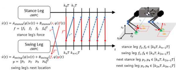
Fig. 4. MSC Quadruped Robot Swing Leg Controller
Traditional quadruped walking controllers often utilized a heuristic approach for the swing leg. However, the heuristic method can lead to potential collisions and may not be optimal, resulting in the selection of unstable foot placements during locomotion. To address this, a controller for the swing leg was developed, with the aim of creating a more stable and robust walking controller using this advancement.
Visual-Inertial External Wrench Estimation
Estimation of the external wrench is necessary to respond to disturbances and interact with the environments. We used a factor-graph based approach for estimation which is widely used in SLAM research. However, these methods do not generally use system dynamics. Since the dynamics also depend on position and velocity, they can be tightly coupled through additional residual construction. Based on this principle, we proposed an external wrench estimator for legged robots.
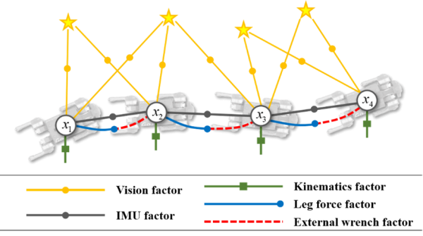
Fig. 5. Illustration of the factor graph. The graph includes measurement factors such as the IMU factor, vision factor, kinematics factor, leg force factor and external wrench factor. We added the last two factors to the existing studies. The external wrench is obtained as shown in the red dotted line.
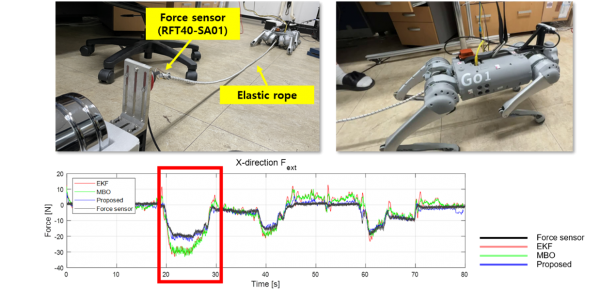
Fig. 6. Experiment setup and results. The results show that the proposed method achieves a high estimation performance compared to other methods.
Force Torque Sensor
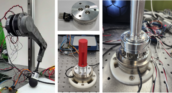
Fig. 7. Force Torque Sensor and Experiment Setup[1]
The force-torque sensor has been developed as a 6-axis force-torque sensor, demonstrating high accuracy along with rapid responsiveness using a photocoupler. It was designed to be compact, allowing for internal processing without the need for external devices like a DAQ, and it communicates using CAN communication. Furthermore, a calibration method has been developed using a control approach. Research is ongoing to accurately calibrate without the need for expensive equipment using this method.
<Reference>
[1] Hyun-Bin Kim, Keun-Ha Choi Kyung-Soo Kim” ACompact Optical Six-Axis Force/Torque Sensor for Legged Robots Using a Polymorphic Calibration Method” arXiv:2309.04720v1
[2] Jeong, Seok Hwan, Kim, Kyung-Soo, Kim, Soohyun "Designing Anthropomorphic Robot Hand with Active Dual-Mode Twisted String Actuation Mechanism and Tiny Tension Sensors" IEEE ROBOTICS AND AUTOMATION LETTERS, v.2, no.3, pp.1571-1578, 2017.
[3] Ji-Chul Kim, Kyung-Soo Kim, and Soohyun Kim, "Note: A compact three-axis optical force/torque sensor using photo-interrupters," Review of Scientific Instruments, vol. 84, pp. 126109, 2013.
[4] Jeong, Seok Hwan, Lee, Ho Ju, Kim, Kyung Rok, Kyung-Soo Kim. "Design of a miniature force sensor based on photointerrupter for robotic hand" SENSORS AND ACTUATORS A-PHYSICAL, v.269, pp.444-453, 2018.
[5] Jeong, Seok Hwan, Kim, Kyung-Soo, Kim, Soohyun, “Designing Anthropomorphic Robot Hand With Active Dual-Mode Twisted String Actuation Mechanism and Tiny Tension Sensors”, Proc. - IEEE Int. Conf. Robot. Autom., pp. 1571–1578, 2017.
[6] Jeong, Seok Hwan, Kim, Kyung Soo, Kim, Soohyun , "Development of a robotic finger with an active dual-mode twisting actuation and a miniature tendon tension sensor," IEEE/ASME International Conference on Advanced Intelligent Mechatronics, AIM, 2016
[7] 대한민국 / 광학식검출방식의 비접촉식 토크센서의 메커니즘 / 김경수, 김수현, 이동관 / 10-2016-0054753 / 2016.05.03 / 출원
[8] 대한민국 / 포토 인터럽터 센서를 이용한 위치 측정 센서 및 그 센서를 이용하는 하중 측정 센서 / 김경수, 김수현, 이동욱, 구동한, 김지철 / 10-1465427-0000 / 2014.11.20 / 등록
[9] 대한민국 / 1축 포토 인터럽터 힘 센서 / 김경수, 김수현, 구동한, 김병진 / 10-1490831-0000 / 2015.02.02 / 등록
[10] 대한민국 / 6축 힘 토크 센서{6-AXIS FORCE/TORQUE SENSOR} / 김경수, 김현빈 /10-2022-0072314